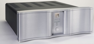
Five Chanel Power Amplifier
The Intrepid is a solid state, fully balanced power amplifier with five built-in channels. The nominal power rating into 8 ohms with one or all five channels driven is 100 Watts/ch. Each channel has single-ended and balanced inputs, and a high-current, dual binding post output connector.
Countries within the European Union will be supplied with a CE-approved version. There is a main power switch on the rear, while the front panel has a push button for standby/on operation. Dreadnaught produces a fully balanced output with either a balanced (XLR type) input or a single-ended (RCA type) input.
Design Concepts:
No Global Negative Feedback
Feedback is a term used to describe an electrical circuit design that applies a portion of the output of a circuit back to the input.
Positive feedback, used primarily in signal-generating devices like oscillators, will not be discussed here.
There are two main categories of negative feedback: global and local. Feedback applied to only one stage is called local. When a feedback path encompasses two or more stages, it is commonly called global feedback. (Nearly all power amplifiers consist of multiple stages of amplification. Intrepid comprises three stages.) Feedback, whether local or global, must occur after the original signal has passed through the circuit. How long after (in time) depends on the speed of the circuit and the feedback path itself.
Local Feedback: Local feedback is very common in almost all analog circuits.
It stabilizes, sets operating points, limits unwanted oscillation, reduces distortion, and protects delicate devices from potential damage. Local feedback is applied almost immediately back to the input, with very little delay. Intrepid contains local feedback in each of its three amplification stages.
Global feedback: Global feedback is also very common in circuit design, but less so than local feedback. It is usually applied to reduce distortions and lower output impedance. It can be used to stabilize circuits that are unstable on their own.
There is significant time delay between the input signal and the feedback signal, due to the number of stages the input signal must pass before being applied back to the input in the form of feedback. Additional circuits must also be used in the feedback path to make sure the negative feedback never becomes positive feedback at any frequency. Because of the significant time delay, global feedback can cause a smearing of imaging and an upper midrange with harshness or glare. The audible effects of global feedback vary, mostly depending on the amount of feedback but also on the circuit they are correcting.
Nearly all power amplifiers use global feedback in large proportions.
Intrepid contains no global feedback at all. The result is a very clean, pure, and fast circuit from input to output.
Dynamic power
Many home audio amplifiers are grossly underpowered for serious music and home theater enthusiasts. Intrepid is fully capable of delivering 100 watts into 8 ohms, 200 watts into 4 ohms and even more into 2 ohms. The dynamic headroom of the Intrepid allows it to deliver even greater power than these steady state ratings.
Reliable
A chief design criterion was high reliability.
Every channel undergoes four major test procedures:
First, after initial assembly, the channel is tested for basic functionality.
The channel is inserted into a bench-reference Intrepid and every parameter is tested, including full power with load at four and eight ohms. All adjustable parameters are set.
The fully tested module is then inserted into a new Intrepid chassis. Each channel in the Intrepid is again tested to verify it is fully functional. The Intrepid then undergoes a torturous burn-in period.
Following burn-in, each channel in the new Intrepid undergoes its final test.
Stages:
An amplifier stage is a section of an amplifier with an input and an output and fulfills some purpose, such as voltage amplification. Generally speaking, the fewer the number of stages the better. In Intrepid, each amplifier module consists of three stages. The first stage provides the high input impedance necessary for any preamplifier to drive and initial voltage amplification needed to drive the speaker. With two volts of input, this stage will produce 5 volts of output. The second stage provides additional voltage amplification and also current amplification needed to drive the third and final output stage. With 1.5 volts of input, this stage will produce a minimum of 28.5 volts of output, enough to drive an 8 ohm speaker at 100 watts.
However, the second stage alone does not have the current delivery necessary to drive the speaker. The third and final stage provides the pure current delivery necessary to drive the speaker.
Amplifier Stage Topologies
The input stage consists of four precision matched J-fet transistor operating in the zero-temperature-coefficient region. They are arranged in a complementary common-source differential amplifier topology, using two n-channel fets and two p-channel fets. This stage is very fast, has high input impedance, and is highly stable. The first stage is directly coupled to the second stage, with no coupling capacitors or other dc correction circuits used.
The second stage also consists of four FET transistors, although in this stage they are MosFets chosen for their high current drive capability and superior electrical characteristics. The topology is similar to the first stage but in this case it is a complementary common-gate amplifier consisting of two n-channel devices and two p-channel devices. The MosFets are hand selected and matched to assure the best possible sonic and electrical performance.
The third and final Intrepid amplification stage consists of 8 high-power, Motorola bipolar output transistors in a fully balanced differential complementary emitter follower configuration, with specialized MosFet pre-drivers. That adds up to a nominal device capability of 128 Amps / 1600 Watts for each 100 Watt channel! This ensures safe and reliable operation under all conditions. All output transistors are tested for output power and matched for ideal linearity.
DC Servo
A unique DC-servo for each channel in the Intrepid eliminates the manual adjustment of DC offset at the amplifier outputs. Conventional amplifier servos encompass the entire signal path, resulting in a global feedback effect. Intrepid's servo is limited only to the output stage, strictly adhering to the zero global feedback design of the original Dreadnaught amplifier. Based on a high quality Fet-input circuit, it employs a long time-constant and is highly buffered. Extensive listening tests ensured that it is non-intrusive on the audio quality, and does not impose an overly damped quality on the sound of low frequency bass or percussion.
Power Supply
The power transformer and output stage bridge rectifier are common to all channels in the Intepid. There are three separate secondary windings: a high current winding for the output stage; a high voltage winding for the input and driver stages; and a third winding for the control circuitry. Each channel has its own capacitor bank for the output current gain stage. There are highly specialized fully discrete regulation circuits for the input and driver stages.
This regulation has MosFet pass transistors to provide fast, clean rails to the voltage gain stages. A separate regulation stage is used for the control circuitry.
There has been considerable debate on the subject of power transformers in a multi-channel amplifier. Some manufacturers provide a transformer for each channel; others divide the amplifier into one two-channel section with its own transformer and another three-channel section with its own transformer. Intrepid uses a single massive 1100 VA power transformer and a 35 Amp bridge rectifier for all five channels.
The inherent benefit of this approach is that any single channel confronted with a full-level signal will have the entire current capability of the transformer at its disposal. In fact, in single-channel power tests, the output power is not in any way limited by the power transformer. The same logic holds true for multiple channels being driven; unless all five channels are driven to full power (which never occurs in real-world situations), the channels not being driven hard effectively "lend" their portion of the transformer's power to the more active channels.
Control Circuitry
The Intrepid features a Standby mode (front panel push button) which mutes and reduces idling current to all channels. This control can also be activated via a remote control jack on the back of the chassis, which would bring a trigger signal from another unit, such as a Casablanca or Casa Nova. There is also a bi-directional RS-232 port.
Connected to a computer or other control device (e.g. AMX or Crestron), the Intrepid's Standby mode can be activated, and status information about the rail fuses, thermal sensors, and mode can be continuously monitored.
Components
Only the highest-grade electronic components are chosen for Intepid. Wima film capacitors are used exclusively for power supply bypassing. Nichicon electrolytic capacitors were chosen for power supply filtering due to their superior long-term performance and audio characteristics. Three and four layer custom manufactured glass-epoxy circuit boards, with heavy copper plating, were specified to carry the high-currents Intrepid can produce.
